12 minutes
Love is in the air: Reverse Engineering a shitty drone
On March 9, 2018, (hey, better late than never :), Security Jam, a security meeting/conference, was held, where speakers present their Research in a relaxed environment.
Last year I was lucky enough to be able to participate as a Speaker giving a talk called:
Love is in the air: Reverse Engineering a shitty drone.
In addition to the Security Jam, I presented this talk at CharruaCon and 8.8 Chile, two highly recommended conferences for those who have not attended!
Here you will find out the details of the talk and, of course, will have access to the created code ;)
TL;DR
Research carried out on a SYMA X5SW Drone with three defined objectives.
Intercept the telemetry of the Drone and display it in a graphical interface in real-time.
Create a transmitter (command control), using RF, Arduino modules and C code.
Intercept the video stream of the camera and look for vulnerabilities in it.
First, we will talk about some basics of radiofrequency, tips to start a project of this type and the problems that occurred throughout.
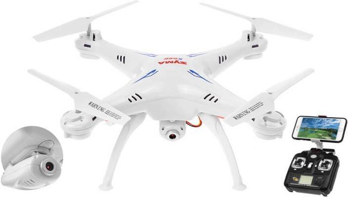
The research started with a SYMA X5SW, after playing a bit with it, it occurred to me if I could try to reverse engineer and understand its communication protocol to “hijack it”
Objective 1: Intercept the telemetry of the Drone.
The idea behind this objective is to be able to capture the packages in mid-flight, as well as understand the communication protocol in order to obtain what the actions sent by the controller are and finally show all the information in a graphical interface!
The first thing we want to find out, is what channel of communication is being used by the transmitter and the drone to communicate. Then, we want to know what hardware we need, the possibilities are:
Wifi
Radiofrequency
Bluetooth
To find this, we have several ways to do this:
Open the transmitter and recognize the chipsets used, then search the internet until We find the manual and its specification.
Read the manual and the box of the Drone because usually they specify this information in most cases.
Search by the FCC-ID.
The first two options are the best known and used, but the last one not many people know about and can accelerate everything a little…
The FCC (Federal Communications Commission) is a US government agency that is responsible for analyzing all devices working with radiofrequency and makes comprehensive reports about the capabilities of these devices.
Manuals of the manufacturer, internal and external photos of the device, specifications of the chipsets used, a gold mine!
All this information, fortunately, is publicly available at https://fccid.io/
In our particular case, we found the information we were looking for:
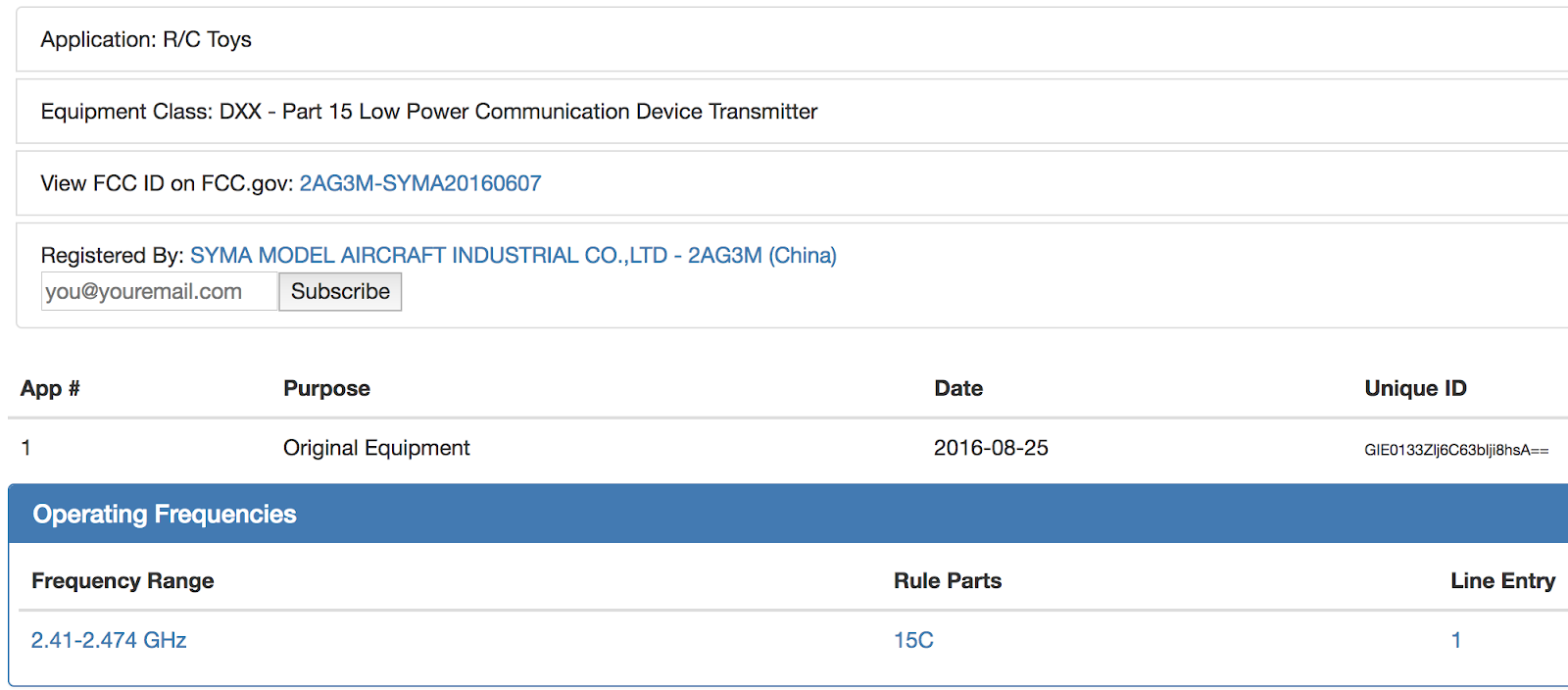
As you can see, the model we find in the database is different from the model that we were investigating, but reading carefully the report found it is mentioned that the electronics included in that model are the same for the one we are investigating.
Finally, if we looked at the box we found some information…
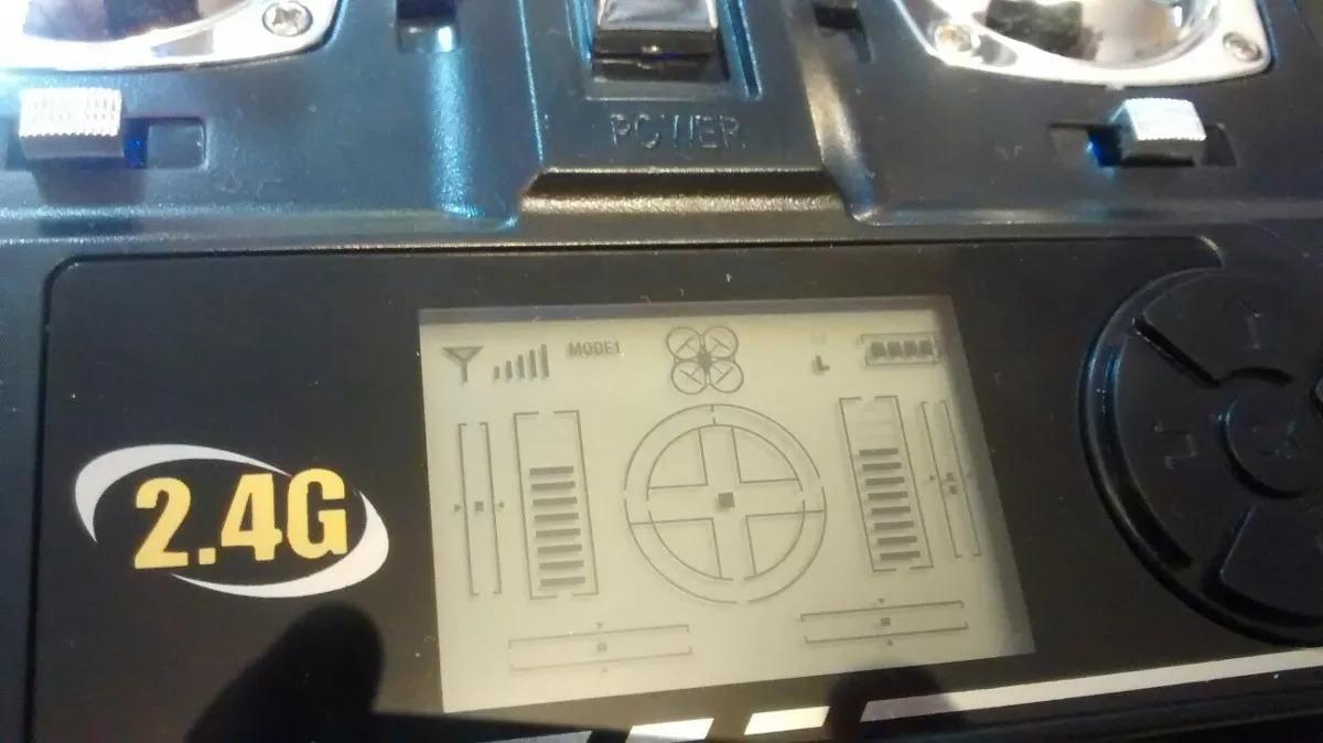

It seems that the report did not lie, 2.4Ghz and apparently works with four channels (Of which we are only interested in 1, I will explain this in-depth later).
Perfect, we have the frequency!
The problem is that we need more expensive hardware to be able to do the research, since the majority of SDR dongles of the RTL2832U style only reach up to 800 Mhz.
Here we have two options:
Use an RTL2832U dongle, with a 2.4 Ghz downconverter that will lower the frequency down to approximately 400 Mhz which is supported by the Dongle.
Use the HackRF / BladeRF, which supports that frequency and has a wider bandwidth.
In my case, I used the HackRF because it was what I had at hand.
The next step is to start working on intercepting the signal and flight packets.
Due to my little knowledge in this field, I decided to investigate a bit on the Internet about this…
And I was lucky…
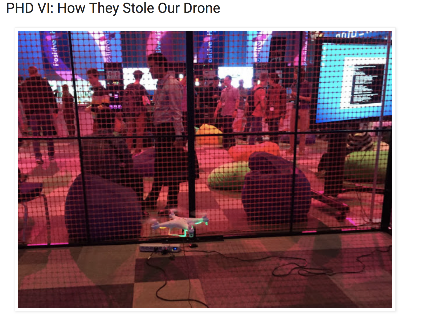
There is a conference that takes place in Moscow, Russia, called Positive Hack Days, where there was a challenge that was based on hijacking a Syma brand drone. After finishing the challenge, they created a blog post explaining all the technical details of how they achieved this and they had a functional receiver and transmitter.
All the code developed is at https://github.com/chopengauer/nrf_analyze
The first step is to test the receiver and transmitter created by them and see if it works with our Drone.
Clone the project: git clone https://github.com/chopengauer/nrf_analyze
Install the HackRF and GNU Radio in our Operating System. A tip for that: GNU Radio in the Ubuntu repositories does not work correctly, so it is necessary to compile from the source. If you use MacOS you can use Brew.
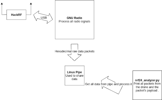
Connect the HackRF and open the GNU Radio template.
Run the python script nrf_analyze.py: You have to change the following line to get the correct PIPE data:
https://github.com/chopengauer/nrf_analyze/blob/master/nrf24_analyzer.py#L65
If everything works correctly, we can use the Drone and we should see the flight packages.
Unfortunately, we do not see any package, so we have to analyze the code and find what the problems are.
Reviewing the code, we can find some hard-coded data such as addresses, routes to PIPEs, channel numbers, etc. Because of this, we may not have been able to capture any flight pack in our previous test.
Let’s review each of the points mentioned
1. Frequency
Thanks to the FCC report we know that the frequency of operation of the drone is between:
2.41 - 2.474 GHzWe will check this in the next step when searching for bandwidth and channels.
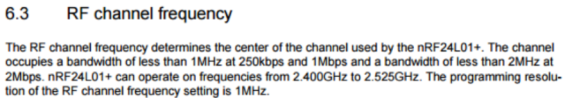
2. Channels
A radiofrequency channel is a way to separate and identify a group of frequencies, which will be used for the transmission or reception of data.
In our case, reading the manual of the transmission module that is used we can obtain a separation of 1 Mhz, which gives us 125 possible channels (2,400 - 2,525 Ghz).
So now, using the nrf_analyze project again, we can load in the GNU Radio nrf.grc and connect our HackRF to look for the channels, according to the drone box, there are supposedly 4.
Now we start the nrf.grc template and we need to change the channels, we used the original transmitter of the Drone to transmit movement commands and see if we could find the signal, and so we changed channels one by one
In the end, we found that the channels are:
22, 26, 30, and 34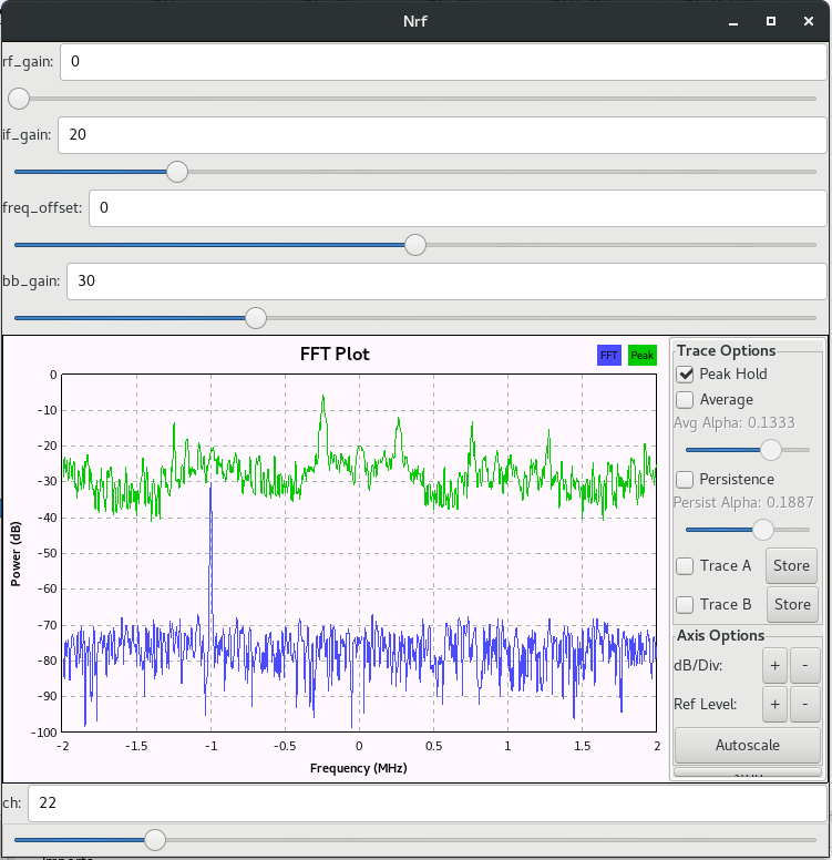
3. Address of the drone
What is this exactly?
If we think that the communication of the data is done through radiofrequency, that as we saw, this has a fixed spectrum range and also fixed channels, this means that if we fly two drones of the same model one next to the other would not be possible.
This is because one would be transmitting and causing noise for the other drone.
To avoid this, there is the address that is sent in the transmitted data itself and that allows us to identify for which device that data packet is directed. With this, it is possible to have two drones flying in the same physical space!
To find the mentioned address, we opened the previous GNU Radio template and we configured one of the channels that we found previously. We create a linux PIPE and we placed it in the GNU Radio template to start the nrf_analyze tool and started to see the flight packages.
In the end, we ended up finding the address of the drone looking at the first bytes of the packets:
a1ca192dbc4. Bandwidth and bit-rate
To obtain this information, we used the FCC manual that we found earlier.
Bandwidth 800 kHz for 250 kbps rateAll ready, recapitulating a little the differences lie in the Channels and the “Drone Address”. Everything else does not need modification …
The payload and its format
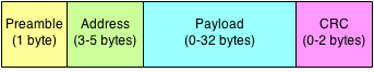
Reading the transmission manual we get with the data format transmitted, the image explains everything quite well.
A byte is used as a preamble, which the receivers use to identify data packets entering, then the address that we explained above, it is used as an identifier, a payload that is the data that we are interested in transmitting and, finally, a CRC of 2 bytes to make sure we receive the payload correctly.
Below you can see an example of the payload and the meaning of each important byte:

- Engine accelerator.
- Tilt (Forward or backward) (*)
- Rudder (Turn on axis) (*)
- Ailerons (left or right tilt) (*)
- CRC (XOR of the first 9 bytes + 0x55) (*) (Higher bit = direction, remaining bits = value)
Now we have everything you need to create the intercept script!
droneTelemetry.py
- Class DecoderSymaX5SW: Parses every byte of the flight packet, returning an action.
- Class DisplayDrone: Using urwid, it shows a graphical interface with the actions of the drone.
Telemetry in real-time :)
Objective 2: Transmit orders to the Drone.
Here the interesting part begins, the idea is to create a transmitter that is capable of sending orders to the Drone, just as the original controller does.
For this we are going to need a couple of things:
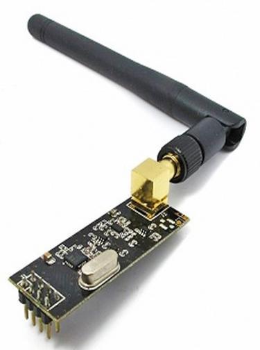
1. A radio frequency transmission module
The NRF24 module is the one usually used in most of these devices, in the case of our original controller, it uses a cloned version of the original module.
The good thing about this module is its price (Three - Five USD) and that it works on Arduino, Raspberry Pi and BeagleBone.
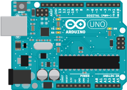
A device where to run our code and connect our transmitter
We need to take special care about this since in other electronic or IoT projects, choosing between an Arduino, Raspberry Pi or BeagleBone is personal taste.
In this case, the latency factor and transmission speed is critical, we need to have the minimum possible latency between the code and the transmission module so that in a matter of milliseconds our packets are transmitted, otherwise the drone would literally fall to the ground.
For this reason the choice is Arduino, for the absence of a complex and heavier operating system that punishes the performance when executing the code.
Now that we have all, it is time to connect everything (Which is not a simple task since there is little information available on the internet about this).
The following table explains pretty well how to connect the module, and was obtained through trial and error…
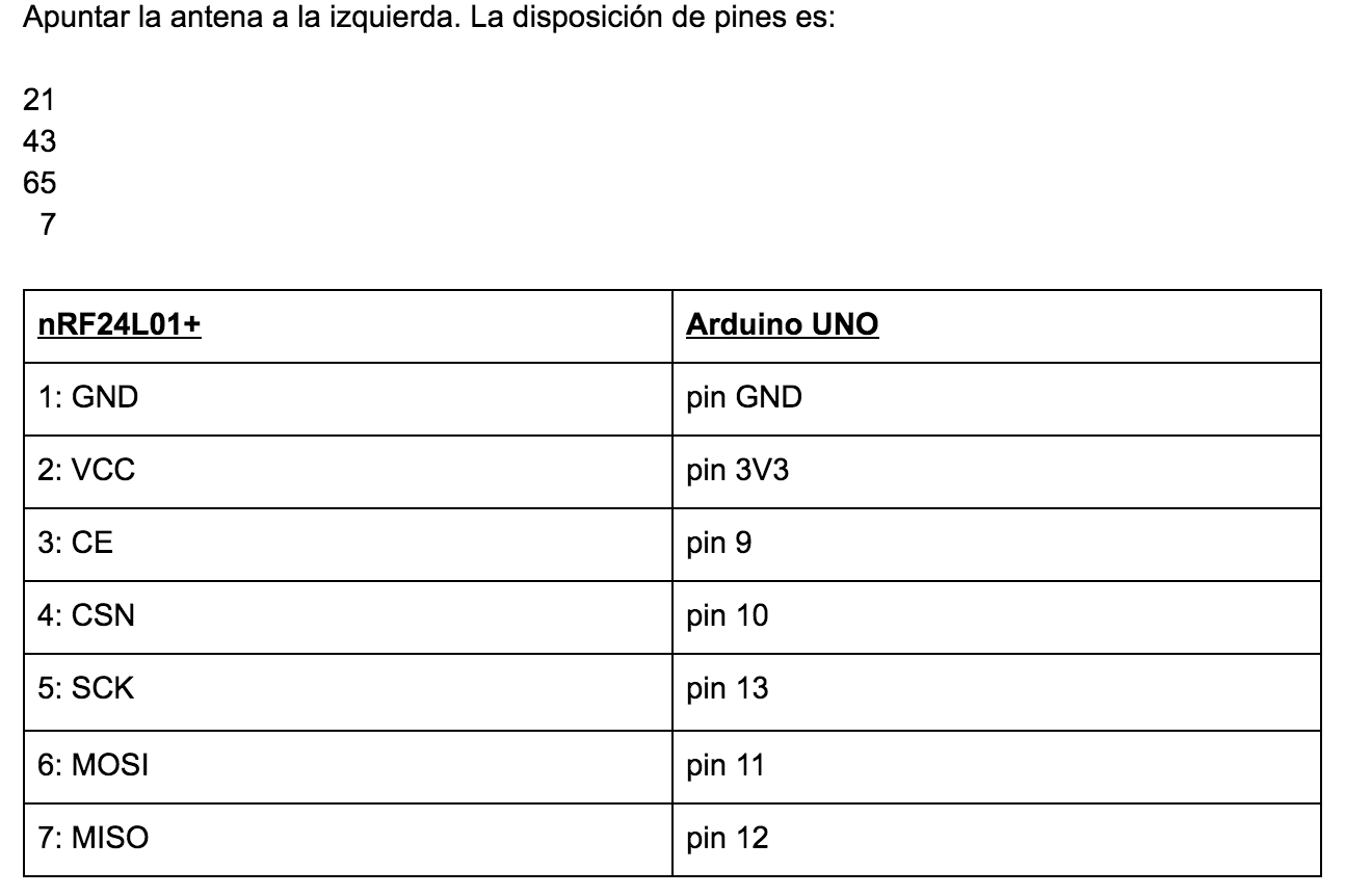
Now, remember the issue of the four transmission channels that the box mentioned and the manual of the FCC? Well, it turns out that it is not like that at all. Transmitting in a single channel we can send orders to the Drone, and it is not necessary to change and transmit on all four channels.
Below, some parts of the transmitter code and a brief explanation of the most important parts
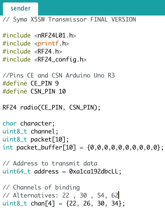
sender.c is developed in C and allows us to send orders to the Drone, as if it were the original controller. The most important thing to mention for the code is the definition of the pins CE and CSN of the module, which in this case are nine and ten. This is the definition of the address previously found and the channels to which we are going to transmit.
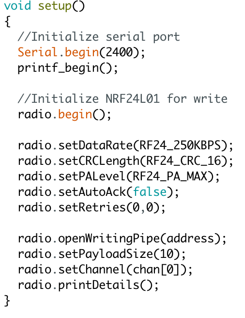
The bauds are defined for the serial connection of the Arduino, and to be able to obtain debug information for our code. In addition to some of our own configurations of the module such as, for example CRC of 16 bytes. Maximum transmission power and “Bitrate” of 250 KBPS, including the transmission channel and the size of payload.
With this transmitter and the lack of an association protocol between the original Drone and Controller, “to hijack” the drone is a matter of having a transmitter with more power and reach than the original!
We did it!
Objective 3: The camera
To connect to the camera, an application that connects to the WI-FI Access Point created by the camera itself is necessary,and using our cell phone we can watch the video streaming, and take screenshots.
Now, if the idea is to “hijack” that video connection, let’s look a bit at the Android application to see how it connects to the camera …
Decompiling the APK we found some things that caught our attention:
Connections to a hardcoded IP: 192.168.1.1 the IP of the camera.
A URL with hardcoded credentials: http://192.168.1.1/request_av.cgi?user=admin&pwd=
A scan of ports for the camera shows us two open ports: 80 and 2345.
The manufacturer of the camera has published documentation and in it we found a way to enable the telnet service, making a request to the URL http://192.168.1.1/set_params.cgi?telnetd=1&save=1&reboot=1
And when we do it …
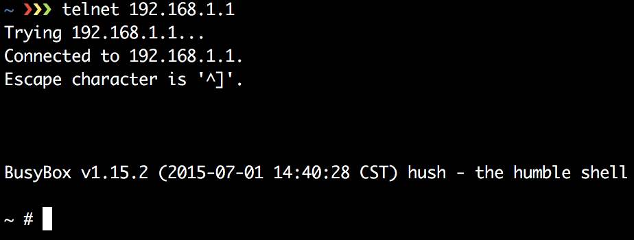
Root Shell, quite simple …
We continued reading the documentation and found that using the URL http://192.168.1.1/snapshot.cgi?user=admin&pwd=
We can take a photo using the default credentials that we found in the APK.
And the video stream?
It is also in the documentation explained!
First we request a stream ID: http://192.168.1.1/request_av.cgi?user=admin&pwd=
Then, we used that ID obtained previously to request the video stream: http://192.168.1.1/videostream.cgi?user=admin&pwd=&stream=714546261
And we have the video stream!
Conclusions:
We intercepted the telemetry of the Drone, we managed to “hijack it” along with its video stream.
We had several problems with the transmission. We solved it using a power bank to supply the peak of energy required by the transmission module, Arduino and C, to improve the transmission performance.
There is no security in the communication: neither encryption nor protocol of secure association. The one that has the transmitter of greater power basically gains control of the Drone.
We were able to intercept the drone’s telemetry and we managed to hijack it along with the video stream!
It should be noted that when I started with this project I did not have knowledge about Radiofrequency nor about SDR. With curiosity and perseverance, and internet connection, you can achieve great things :)
Now, it’s time for another project.
All the developed code available in: https://github.com/Ezequieltbh/SymaX5SW-Rx-Tx
Slides of the talk: Slides Github
Translation into English:
Fabrizio Scaglione
Josh Mador
Special thanks to all people that help me with this project! You know who you are…